Monday, September 8, 2014

From zero to lighting in 2D

This tutorial is about spicing up your 2D game with some awesome lighting. I made this tutorial because there aren't any out there yet, and it's a very cool effect to add to your 2D game.

What you need to know

First off, I assume you have some familiarity with C#, or coding in general. Secondly it is advised to at least have programmed in a shader language before. Used in this tutorial is HLSL. The rest is what this tutorial is for!

The final result

You can download the code example here (or you can scroll down to find some explanations). The final result will look something like this:


Normal maps

Normal maps are textures to containing a color indicating the normal of a certain pixel. How does this work? Take the normal map used in the code example alongside the original texture:


The left texture contains the normal colors, and on the right is the generated color defining the normal. To calculate the actual normal vector, we have to apply a little transformation:
$$normal = 2.0 * pixelcolor - 1.0$$

To explain this better, we take the most common color in the picture, a light blue-ish color. In RGB values it is about $((128, 128, 255)$), which is reduced in the range of [0,1]as $((0.5, 0.5, 1.0)$). After applying our transformation the value becomes $((0.0, 0.0, 1.0)$) which is a normal pointing in the Z direction.

In our 2D game this value will point from screen towards the viewer. As you can see in the normal image, there are several red and green colored portions, which will affect the direction of the normal. With this information we can add fake depth to a plain 2D texture!

The drawing setup

To pass this information to our lighting effect we need to have this normal map ready, which means we can't draw everything on the screen immediately. The setup used for this comes close to Deferred Shading. We only need the color and normal buffer, since the depth buffer is worthless here.

All the normal sprites are drawn first, as you're used to, except, this time we save them to a rendertarget. After which I draw all of the normals to another rendertarget. Unlike standard deferred shading, I chose to render the lights to a seperate rendertarget here. If you wish, you can combine drawing the textures and drawing the lights to a single pass. This was merely done to show the different rendering steps here.

The actual lighting magic
Because it's a 2D game, you expect to need to draw a "lighting texture", something like this:


But we don't need to! Since we have a normal, we can simply apply the technique to draw a light in 3D, which is really fancy and easy to create. The effect I used to create this tutorial with is called Diffuse Reflection, or Lambertian Reflectance. We set up a point light (which is, a point from which light emanates) and calculate the pixel color on the GPU.

Diffuse reflection requires three things: the position of the light, the position of the current pixel being shaded, and the normal at that position. From the first two you can calculate the light direction, and by looking at the value of the dot product from the light direction and the normal you can determine the lighting coefficient.

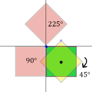
Sometimes you will want to rotate the normal retrieved from the normal map. This is done by creating a separate rotation matrix and adding it to the shader. More information about creating such a matrix can be found in my other tutorial series on rotations.

Finding the correct normal on the pixel position is rather easy: we have a full screen buffer of normals, and a position given by the draw call. Dividing this position by the screen size, we have the texture coordinates of the normal pixel ranging in [0,1]. Exactly what we need!

Code example

All of this code can be found in the source code, I'd like to point out a few things in this article though, here's the code used for lighting in HLSL:
// Basic XNA Vertex shader
float4x4 MatrixTransform;
void SpriteVertexShader(inout float4 color    : COLOR0,
     inout float2 texCoord : TEXCOORD0,
     inout float4 position : SV_Position)
{
     position = mul(position, MatrixTransform);
}

float4 PixelShaderFunction(float2 position : SV_POSITION, 
         float4 color : COLOR0,
         float2 TexCoordsUV : TEXCOORD0) : COLOR0
{
     // Obtain texture coordinates corresponding to the current pixel on screen
     float2 TexCoords = position.xy / screenSize;
     TexCoords += 0.5f / screenSize;

     // Sample the input texture
     float4 normal = 2.0f * tex2D(NormalSampler, TexCoords) - 1.0f;

     // Transform input position to view space
     float3 newPos = float3(position.xy, 0.0f);
     float4 pos = mul(newPos, InverseVP);

     // Calculate the lighting with given normal and position
     float4 lighting = CalculateLight(pos.xyz, normal.xyz);
     return lighting;
}

// Calculates diffuse light with attenuation and normal dot light
float4 CalculateLight(float3 pos, float3 normal)
{
   float3 lightDir = LightPosition - pos;

   float attenuation = saturate(1.0f - length(lightDir) / LightRadius);
   lightDir = normalize(lightDir); 
 
   float NdL = max(0, dot(normal, lightDir));
   float4 diffuseLight = NdL * LightColor * LightIntensity * attenuation;
 
   return float4(diffuseLight.rgb, 1.0f);
}


As you can see, the shader consists of a vertex and pixel shader. The vertex shader simply passes on the color, texture coordinates and position. It only transforms the position with the given matrix. After the vertex shader we know the rectangle on the screen and the pixel shader will analyze all the pixel inside of it.

What you first see in the pixel shader is getting the texture coordinates from the position. This is done by dividing it through the screen size and adding half a pixel width (so we're in the center of the pixel). With this coordinate we can sample the normal map to get the color of the normal, and as shown in this article, calculate the actual normal from it. What happens next is retrieving the original position, by multiplying it with the inverse view-projection matrix. We can now calculate the lighting with given parameters.

Where the light calculation method is nothing more than a normal times lightdirection to see if the surface should get lit. Of course, not to forget, the attenuation which looks at the range of the light and caps it (smoothly) by multiplying it with this value.


Optimization

You want to draw a lot of lights, right? Normal deferred shading can't handle a lot of point lights, since you have to redraw the whole screen for every pointlight. Thus follows the first optimization: if we only draw a small square on the screen were we expect the light to shine, we don't draw the rest of the screen. This is done quite simple by adding a light radius, from which we can create a rectangle to draw in spritebatch.

Since we don't need to draw any textures, and we still have to make a draw call, I found the following optimization: in spritebatch you have to supply a texture for a draw call, the best way to use our previous optimization is drawing a pixel and upsize it to the square. This way, the pixel shader can sample the normal map and output the lighting on the positions given by the draw call. In the code I just pass the normal map as texture for simplicity.


I hope you learned something from this tutorial, and sure hope to see some awesome games created with this effect!

Friday, May 9, 2014

Bloomifier

I spent some time working out an idea that randomly popped into my head. I thought: XNA runs in windows forms, is it possible to add some Windows functionality to the XNA window? Turns out it was!

By just adding some simple form code in XNA, you can treat the window as a form. Which of course lead to some fun ideas to work out. My idea: Drag & Drop a picture into the XNA window, then load it as Texture2D. After we have succesfully retrieved this texture we can add some bloom to make it interesting.

Here is the (simple) code to get the FormHandle and allow for files to be dropped into the screen:
form = Form.FromHandle(Window.Handle) as Form;

if (form == null)
{
throw new InvalidOperationException("Unable to get underlying Form.");
}

// We must set AllowDrop to true in order to let Windows know that we're accepting drag and drop input
form.AllowDrop = true;
form.DragEnter += new System.Windows.Forms.DragEventHandler(form_DragEnter);
form.DragOver += new System.Windows.Forms.DragEventHandler(form_DragOver);
form.DragDrop += new System.Windows.Forms.DragEventHandler(form_DragDrop);


Of course you still need to define these functions DragEnter, DragOver and DragDrop yourself.

Once I had this, I added a little bloom effect and combined this with the original. The result was pretty cool:


Here's the link: Bloomifier. To succesfully run this on any Windows system, you need the XNA redistributable: XNA

Friday, February 14, 2014

Using Git for version control part 2

In the last part of the previous tutorial you already used some git commands like clone and push. Most of the git commands are pretty straightforward and do exactly as the name says, even though, I will still explain briefly what the command is used for and how to use it.

Commit:
The Commit command will open the staging window, in which you can select all of the files you want to commit to your local branch (more on branching below). For now remember that this will not affect the remote repository but only save the changes to your local working space. Committing your changes is necessary if you want to switch branches. A commit is also good to just save your temporary changes to the code to come back working on it later.

Push:
This command will upload your committed work to the remote repository. Usually done in combination as "Commit & Push" from the previous tutorial.

Pull:
The pull command will open a pull dialog in which you can select some options:


In the example above we want to checkout the remote branch 'master' to our local branch 'master'. We also specify that we only want to fetch the remote changes and not merge or rebase anything, since it is the same branch.

Fetch
The Fetch command can be found in the pull drop-down menu:


It will update all pointers to existing branches from the remote repository. For example: someone else made a change to the master branch and committed to the remote master branch. If you press the fetch command, it will set the pointer from the origin/master branch to a new version shown below:


This says your local copy of the repository is still on the "out-dated" version of this branch on "Test", while there is a new commit already pushed to the origin/master branch shown above it as "New Test".

To retrieve the changes made in this commit you will have to checkout this branch shown below. You could also pull all changes in this branch by rebasing the origin/master in your local repository, the results will be the same (in this case).

Branches:
Branches are what makes Git really useful to work with. For this tutorial we will assume we have two teams working on a piece of software: the first one will focus on the implementation part of the code and the second team is creating a GUI for it. To realise this in Git we can create two branches in our project by using the command "Create Branch" to create "Implementation" and "GUI" branches. The result so far will be shown as follows:


The GUI and Implementation branches are on the same commit as the master and origin/master branches. We will now change our current branch to the GUI branch, apply some minor changes, then commit and push them to the remote repository. When it asks if you want to add this branch to the remote repository, click yes.

Now checkout the Implementation branch and you will see that the changes you have just made to your GUI branch are undone! Talking in SVN terms: you have just created two "seperate" repositories next to each other, one called Implementation and one called GUI.

To continue with the next part of the tutorial, make some minor changes to the Implementation branch as well and commit and push it as you did before. The result will look something like this (you might have to click View -> Show all branches first):


Merging:
In our example from branches, the GUI team has reached a point where they made a few buttons. The Implementation team wants to have these buttons in their Implementation branch, how do we do this?

Change to your Implementation branch, and choose Command->Merge branches (or Ctrl + M). You will see the following window pop up:


As you can see you're currently in the Implementation branch and you want to merge it with the origin/GUI branch (where the other team has pushed their changes). Shown in the example to the left you can see what will happen, the C and D nodes represent changes to your current branch (we have one, called "Test3"). The E and F nodes represent changes the GUI branch, in our example shown as "Test2". This merge will combine these changes to your local branch of Implementation. If you don't run into any conflicts (e.g. you haven't changed anything on the same line in any file) it will merge automatically and the Implementation team will have their fancy buttons. If however you did change the same line in a file, you will run into a conflict.

File conflicts:
We tried to merge two branches and Oops! We got a file conflict! Click "Resolve conflicts" to get to this next window:


As you can see, there is a conflict in the .gitignore file. File conflicts are solvable withing Git Extensions (actually they are solved by KDiff3). Click on the "Open in kdiff3" button to get this next screen:


You can see you have 3 files, shown with red underlines they are your Base file, Local file (from your local branch, Implementation) and the Remote file (the file from the GUI branch). You can see that there are different versions in both branches. The output will be the bottom most screen. To solve the conflict you can press the blue A, B and C buttons on top or even manually type it in the bottom code if you want a little bit of both. If you have multiple conflicts you can click on the arrow buttons to automatically scroll to the next conflict to solve. If you are done solving conflicts, save your changes and close this screen.

You will now be asked if you want to commit and push these newly made changes from the conflicts, press commit. After you've done that you successfully merged the GUI branch in our Implementation branch, with the result showing up as follows:


After doing this you can still use your GUI branch to continue working on the GUI. The Implementation branch will have the changes made in the GUI branch from the time of the merge. Even though this example was good to illustrate merging, I'd advise against it and instead merge your changes from both Implementation and GUI branches to the master branch (if it all compiles of course!).

These were the basics of working with Git in the Git Extensions GUI, you can leave any questions or comments below.

Wednesday, February 12, 2014

Using Git for version control part 1

This tutorial is about version control using Git. For this tutorial I will assume you are familiar with some kind of source control, for example SVN. We will skip the basics of how all source control works and just focus on working with Git in this case. The Git workflow is most commonly used for open source projects, because it's excellent for communication and coordination. In this tutorial, however, we're aiming to use Git for a private repository, and in order to achieve that you will need an account on Bitbucket. If you're a student, you can get some free private repositories on GitHub too!

Installing required software:
Git Extensions: The GUI we will use in this tutorial, Git Extensions, is the most suitable GUI for larger software projects, because it uses KDiff3 to solve conflicts (more on conflicts in the next part of the tutorial). If you work alone, or you know you will not bump in any file conflicting scenario's it's easier to download Github's GUI. This will not be covered in this tutorial, but it's fairly easy and straightforward to use once you know the basics of Git.

Git Extensions has its own version of Git included, if you want the newest Git, you can download it here: Git for windows. This installs the basic source control management.

Setting up a repository:
If you are joining an already existing project you can skip this step! Just make sure you are invited to the project (if it was a private one) and that you can reach the actual repository.

Once you log in to your account on Bitbucked you will see your dashboard and from there click the Create or Create repository button. You will see a screen like this:


Here you will have to name your project and choose which kind of source control you are going to use, in this case it will be Git. The Access level is automatically set to private, which means (at first) only you can reach this repository, which is desired. You can also choose to have Issue tracking which is basically a neat function to report bugs and couple them to this repository. The Wiki option allows you to create documentation for the current repository. Finally there are some language specific options which will set you up with some basics for the programming language in your repository.

Once you have done this, you're done setting up your repository and it's time to clone it and get started.

Cloning an existing project:
From here on, we will use the Git Extensions GUI. The first time you start Git Extensions you will probably have to fill in some personal information like your username. After that you will arrive at your Dashboard, which will most probably be empty. Listed among the Common Actions, or alternatively in the Start menu, you will find the "Clone Repository" option. You will see something like this (I already filled it in):


The "Repository to Clone" is the project you want to create a local copy of (or a local directory you want to create a Git Repository of). The rest of the options are about where you want to locate this repository on your PC. The rest of the options (should) be automatically set as seen above. You can find the link to your repository on Bitbucket by going to your repository page and clicking "Clone". Copy&Paste the HTTPS into Git Extensions as I did in the picture and make sure to remove the "git clone" commands at the start (these are done automatically for you by Git Extensions).

Important: If you get the error "fatal: could not read Password for" etc. You will need to run the following command in the Git Bash (Tools -> Git Bash, or Ctrl + G):git config --global core.askpass /usr/libexec/git-core/git-gui--askpass

This will re-enable the notification which asks you to fill in your password instead of directly declining your request.

Making your first Commit and Pushing it to the repository:
If you followed the steps above you will be in your currently empty repository in Git Extensions, looking at the following screen:


Click the "Edit .gitignore" button which will open a new window with a text editor. For now, just click the "Add default ignores" and save the file. This file will tell Git which files should be ignored on each commit so they won't bother showing up on staging each commit. After you've done that, click the "Commit" button, which will open the staging window. Select your newly made .gitignore file and press the "Stage" button with the purple arrow pointing down. By doing this you want to commit only the .gitignore file and nothing else, which is what we want.

To finish this tutorial, enter some commit message and press the "Commit & Push" button which will stage the file to commit and push it to the remote repository on Bitbucket (which you can see on Bitbucket itself if you click on source).

This was the first part of the tutorial showing you how to set up your private repository using Bitbucket. In the next part I will show you the power of Git by using branches and solving file conflicts on commits.

Continue to part 2

Wednesday, January 29, 2014

Mathematics behind rotation part 3

Back to Part 2

In this final part I will show how you can use the last two parts of the tutorial in code for XNA. First we'll look at the Draw command from XNA's SpriteBatch and to conclude this series a little abstraction to rotating 3D models.

XNA is a very powerful game-development tool, and it surprisingly easy to use for rotations. If we want to draw the green square from part 1 in the Draw function from XNA, the code would look like this:
// The standard Draw method
Texture2D square; // Your square texture
public void Draw(SpriteBatch spriteBatch, GameTime gameTime)
{            
    Vector2 position = Vector2.Zero;
    Vector2 origin = new Vector2(square.Width / 2, square.Height / 2);
    float rotation = (float)Math.PI / 4;
    float scale = 1.0f;
    float depth = 0.0f;
    spriteBatch.Draw(square, position, null, Color.White, rotation, origin, scale, SpriteEffects.None, depth);
}

This special overload for the Draw function allows us to rotate the sprite with a certain amount. It takes a radian as input, represented in a float value of $\frac{\pi}{4}$ which equals 45 degrees. I'm not going throught the rest of the arguments you have to fill in as most of them are quite obvious and is out of scope for this tutorial. All of the theory that I've explained about rotations is well hidden in the code of XNA itself. You only have to define an origin and then draw the texture in this special overload of the Draw.

For creating rotations in 3D you will have to use rotation matrices. You can use them to rotate in 2D as well if you use the rotation over the Z-axis of course. To define a rotation matrix you can use the following code:
Vector3 position = Vector3.Zero;
float angle = (float)Math.PI / 4;
Matrix rotationX = Matrix.CreateRotationX(angle);
Matrix rotationY = Matrix.CreateRotationY(angle);
Matrix rotationZ = Matrix.CreateRotationZ(angle);
position = Vector3.Transform(position, rotationZ)

This will create a rotation over the Z-asix for our defined position here. I've also included the X and Y matrices, just for example. These matrices are in fact the matrices we've talked about in the last part. Note here that Vector3.Transform() does not apply any "magic" behind the scenes, it only rotates around the origin. An example to demonstrate this:


The green circle here represents only a rotation applied to an object. If, however, you first chose to do a translation on the object (the red arrow) and then apply a rotation, it will still rotate around the origin, being the center of the axis here. So my tip (and warning) here is to apply the rotations first and then apply other matrix operations. This will make the model rotate on the spot and then translate to the position, which is hopefully the result you wanted :).

This is it for this tutorial series on rotations, I hope you learned something from all of this and definitely hope to see you back for my next blog entry! If you have any questions, you can leave a comment below.

Sunday, January 26, 2014

Mathematics behind rotation part 2

Back to Part 1

In this part I will show how to define a matrix for the rotation. Once we have seen all this in 2D we can rather easily transfer this knowledge, and create a 3D rotation. If you don’t know what a matrix is, you can always look it up on Wikipedia, even though you can understand this tutorial with pretty basic knowledge about matrices!

Continuing from the last part, we’ll have a look at rotation the green square again. Let's first focus on a matrix to rotate our square with a certain amount of degrees denoted by $\theta$. We'll take each point on the square as a vector in 2D. For rotating by an arbitrary degree we can use the following formulas for the x and y:

$x'=x\cdot \cos\theta -y\cdot \sin\theta$

$y'=x\cdot \sin\theta +y\cdot \cos\theta$

This would rotate a vector, initially aligned with the x-axis, $\theta$ degrees counterclockwise. To get our output results x' and y' we have to apply a rotation matrix on the vector. By taking the above formulas we can setup the required matrix to rotate counterclockwise rather easily:

$\begin{pmatrix}x'\\y'\end{pmatrix}=\begin{pmatrix}cos\theta&-sin\theta\\sin\theta&cos\theta\end{pmatrix}\begin{pmatrix}x\\y\end{pmatrix}$

To see this in action, I will provide an example by rotating 90 degrees counterclockwise. Taking the cosine of 90 degrees, or rather, $\frac{\pi}{2}$ radians is equal to 0. And the sine of 90 degrees is equal to 1. This leaves us with a rather easy to use Matrix:

$R(\frac{\pi}{2})=\begin{pmatrix}0&-1\\1&0\end{pmatrix}$

For example, filling in the vector (4, 1) would produce the following result:

$\begin{pmatrix}-1\\4\end{pmatrix}=\begin{pmatrix}0&-1\\1&0\end{pmatrix}\begin{pmatrix}4\\1\end{pmatrix}$

Now we got this all sorted out in 2D let's make a quick stop at creating the same rotation in 3D. We got a brand new vector in 3D with an x, y and z coordinate. To rotate this vector we have to specify around which axis we want to rotate. We will fill in nearly the same matrix as for 2D rotations, only now for the axis we are rotating on. For the other axis we just leave the matrix blank except the multiplier for the coordinate itself, which we want to multiply by 1. A little mindboggle to explain the previous 2D rotation: If you imagine the rotation in 2D, its actually rotating around the (invisible) Z-axis in 3D. If you see that, you will see the next matrices for 3D rotations are no different at all.

$R_{x}=\begin{pmatrix}1&0&0\\0&\cos\theta&\sin\theta\\0&\sin\theta&\cos\theta\end{pmatrix}R_{y}=\begin{pmatrix}\cos\theta&0&\sin\theta\\0&1&0\\\sin\theta&0&\cos\theta\end{pmatrix}R_{z}=\begin{pmatrix}\cos\theta&\sin\theta&0\\\sin\theta&\cos\theta&0\\0&0&1\end{pmatrix}$

If you would fill in our test vector of (4, 1, 0) and rotate it over the Z-axis you would get the same result as before. The only difference is an extra coordinate.

This is all you need to know about matrix rotations to create a nice rotation in 3D. In the next part I will show some code samples on how all of these matrices are predefined in Microsoft's XNA, and how you can use them with the theory from part 1.

Continue to part 3

Thursday, January 23, 2014

Mathematics behind rotation Part 1


This will be a tutorial series on rotating sprites and 3D models. The first part will take you through the mindset of rotation and explain in theory how rotations work. The second part is the more mathematical part about rotation using matrices and applying this for 3D rotations.

This short part of the tutorial will be on rotating sprites. First I will explain about rotation in general, define ‘good’ and ‘bad’ rotations, and after that I will continue by pointing out how we can define this in the ‘digital world’ as I will call it from now on.

Lets start with the basics behind rotation in 2D. Say you have a nice image you wish to rotate shown here as the green square. If you want to rotate it by 45 degrees, you will want to expect the yellow square here. For some of you this will be perfectly normal, and it should be. However, usually when you rotate an image in your code and look at what happens, we see the red squares appear when rotating 90 or 225 degrees. How does this happen, and more importantly how do we fix this?


Going back to the digital world, we have some other sense of logic. It will all make complete sense in a moment but bear with me. An image is usually represented as a 2 dimensional array of information, starting at [0,0] and ending at [X,Y] with X as width and Y as height of your image. So the least you know about your image is it starts at [0, 0], right? Thats exactly why this ‘bad’ rotation from green to the red squares happens. I marked the top left corner of the image with a blue dot, this is the position [0,0] of your image. As you'll see this blue dot will stay pretty much on the axis I’ve drawn. So, if you would just say to your compiler:
"rotate my image 90 degrees!" Your compiler would just say: "okay, I will rotate it around the origin for you, you have not specified anything so I will assume your origin is centered at [0, 0]!" Hence the result shown in the image above shows up.

So how do we fix this? We want to get the result shown as the yellow square above. To realise this we have to rotate the image around its own axis. Shown in the image is the center of the green square with a black dot. What we want to do here is set the axis for the rotation on this point. So basically you just put a hinge in the center of the square and rotate it around that. Now to represent this in the digital world, lets go back to the origin of your image: [0, 0]. We want this origin to be the center of the green square.


For the complete rotation to work you will have to move the square so that the center of the image is positioned at the axis, shown here in the image above. Once you have done this you can rotate your image freely without consequences. At the end don’t forget to return it to its original position!

This was it for part 1 of this tutorial. In the next part we will continue on doing this correct rotation by using matrices and then applying it on 3D models.

Continue to part 2